A CNC machining quality inspection report should let a buyer determine what was inspected, which controlled drawing governed acceptance, how each characteristic was measured, and what the actual result was. A page of checkmarks cannot answer those questions. Useful evidence connects delivered parts to traceable specifications, measured values, material records, and required secondary-process results.
The appropriate package depends on functional risk and production intent. A prototype with ordinary dimensions may need less documentation than repeat production containing fitted bores, multi-face GD&T, controlled surface roughness, heat treatment, or coated precision features.
Procurement, engineering, and quality teams should define this evidence before quotation. Doing so gives suppliers a common acceptance basis and reduces later disputes over report scope, inspection cost, revision control, and missing documentation.
What Part and Revision Details Must the Inspection Report Identify?
Require the report to identify the part number, drawing revision, inspection date, serial or lot number, and responsible inspector or operator. Add equipment or process references where traceability requires them, so every result can be connected to the correct specification, production lot, and inspection event.
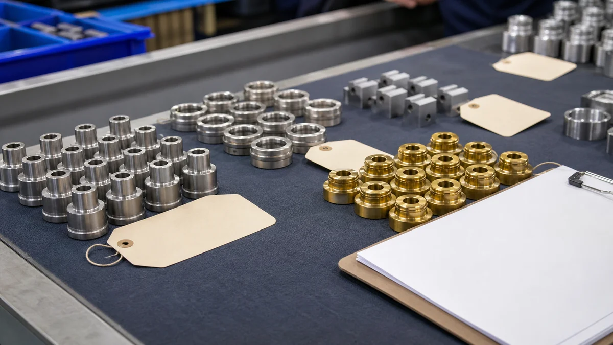
Identification comes before dimensional review. A precise measurement is not useful if the buyer cannot connect it to the correct part, released drawing, and shipment. The report header should agree with the purchase order, packing information, and controlled drawing.
Require the applicable fields from this list:
- Part name and part number
- Controlled drawing number and revision
- Purchase order or job reference
- Serial number or production lot
- Quantity produced and quantity inspected
- Inspection date
- Inspector or operator identification
- Report number and approval status
- Measurement-equipment reference when required
Choose serial or lot traceability according to the order. If parts carry individual serial numbers, the report should show which results belong to each part. If acceptance is by lot, the lot identifier should connect the inspected sample to the delivered quantity and stated sampling scope.
Revision control deserves equal attention. A part can conform to an obsolete print while failing the released design. Require the revision on both the report and the ballooned inspection drawing1 so the two documents cannot be separated without leaving a visible gap.
Example: A housing report lists acceptable bore and mounting-pattern results but omits the drawing revision. Engineering then confirms that the mounting pattern changed in the latest release. The recorded values may be accurate, yet they do not prove conformity to the active design. The supplier must establish which revision was inspected and recheck affected characteristics if necessary.
Put the required header fields in the RFQ or purchase order. Otherwise, a supplier may submit a generic template that records measurements but cannot reliably connect them to the shipment.
Which Actual Measurement Values Should the Supplier Report?
Require nominal values, tolerance limits, actual measured results, deviation where useful, and pass or fail status for every characteristic within the agreed inspection scope. Do not accept OK or NG alone for functional features because it hides proximity to a limit and prevents independent conformance review.

A dimension table should let the buyer reproduce the supplier’s acceptance decision without requesting another explanation. Place the requirement and result in the same row, and state the units explicitly. This matters when the model, drawing, supplier, and receiving-inspection system do not all use the same unit convention.
| Required column | Specification value | Practical consequence if omitted |
|---|---|---|
| Characteristic number | Links the row to the controlled drawing | Similar features can be confused |
| Nominal value | States the design target | The measured value lacks context |
| Lower and upper limits | Defines the acceptance range | Tolerance interpretation remains uncertain |
| Actual measured value | Records objective evidence | Independent review is impossible |
| Deviation | Shows distance from nominal | A result near a limit is harder to recognize |
| Acceptance status | Records conformance disposition | The supplier’s decision is unclear |
| Inspection method | Identifies how the value was obtained | Method suitability cannot be reviewed |
The buyer must also define coverage. Full characteristic reporting may suit a first article. Repeat production might instead require results for selected critical features under an agreed sampling plan. Inspection of every part may be appropriate for a specific high-risk characteristic, but it should not be requested as a general quality signal.
Give priority to features that control fit or function: bearing bores, press fits, sealing faces, dowel holes, mounting interfaces, and aligned hole patterns. Non-contact pockets and cosmetic edges usually do not need the same reporting depth unless the drawing makes them acceptance characteristics.
A common mistake is writing “full inspection report required” without defining whether full means every drawing characteristic, every critical characteristic, or every produced part. State the characteristics, sample basis, reporting frequency, and required actual dimensional results2 explicitly.
How Should Inspection Results Connect to the Controlled Drawing?
Require each reported characteristic to correspond to a numbered balloon on the controlled drawing or an equivalent feature index. The numbering should cover applicable dimensions, notes, threads, surface requirements, and geometric controls, allowing the buyer to find omissions and confirm that inspection used the correct revision.
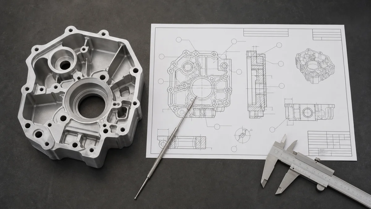
A ballooned drawing assigns a unique number to every characteristic requiring verification. The inspection report uses the same number, creating a direct path from specification to result. This is more reliable than descriptions such as “top hole” or “large bore,” which may refer to several features or become ambiguous after a revision.
The characteristic index should extend beyond linear dimensions. Depending on the drawing, balloons may identify:
- Hole and thread sizes, depths, and quantities
- Edge breaks, chamfers, and deburring notes
- Surface roughness and localized finish zones
- Material and hardness requirements
- GD&T feature control frames and datum references
- Coating, heat-treatment, or masking notes
Requirements verified through supporting records rather than direct measurement should still have a characteristic number. The report can then point to the relevant material record or special-process evidence instead of leaving that drawing note unaccounted for.
Numbering also makes revision review manageable. If a hole pattern changes, the buyer can identify the affected balloons and decide which previous results remain valid. The original report should not be silently overwritten; revised evidence needs a clear record of what changed.
Which file governs acceptance?
The RFQ should answer that question before quotation. The 3D model communicates complete geometry and supports manufacturing planning. The controlled 2D drawing3 normally communicates tolerances, units, datums, threads, notes, finish requirements, and revision status. If the files conflict, written direction must identify the governing requirement before machining and inspection proceed.
Good drawing-to-report mapping is not administrative decoration. It is the control that shows every accepted result belongs to an identifiable specification.
What GD&T Evidence Must the Report Provide?
When the drawing applies GD&T, require actual geometric results evaluated from the stated datum reference frame. Feature size alone does not prove position, form, or orientation. The report should identify the controlled characteristic, applicable datums, tolerance, measured deviation, inspection method, and acceptance result.
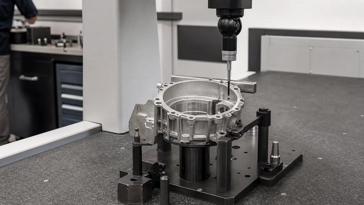
GD&T defines form and the relationships between features. A bore can satisfy its diameter limits yet still be misplaced, tilted, or misaligned with a mating feature. The report must therefore use the drawing’s datum sequence and show the measured result for each specified geometric control.
| Geometric control | Functional question | Reported evidence |
|---|---|---|
| Position | Is a hole or pattern correctly located? | Datum frame, tolerance zone, measured positional deviation |
| Flatness | Is the controlled surface sufficiently flat? | Measured form deviation and evaluation condition |
| Perpendicularity | Is the feature square to its datum? | Referenced datum and orientation deviation |
| Parallelism | Does a face or axis remain parallel to a datum? | Datum reference and measured deviation |
| Roundness | Is the evaluated cross-section sufficiently round? | Measured form result at the stated section |
| Cylindricity | Is the complete cylindrical surface controlled? | Overall measured form deviation |
Only drawing requirements should become acceptance controls. An informal check does not replace the specified characteristic, while unnecessary GD&T on cosmetic geometry can increase machining and inspection effort without protecting assembly function.
Scenario: A machined housing has a bearing bore with an acceptable diameter. Its axis, however, must remain perpendicular to mounting datum A and positioned from datums A, B, and C. Diameter alone cannot prove alignment. The report needs measured orientation and position results within the defined datum reference frame.
Inspection scope must also state whether every part or a sample is measured. For thin walls, broad plates, and multi-setup geometry, define whether results apply in a free state, supported condition, or agreed fixture. Otherwise, unclamping or inconsistent support may change the reported form even when the same feature is being evaluated.
How Should Measurement Methods Match Feature Risk?
Choose measurement methods according to feature geometry, accessibility, tolerance, datum relationships, surface condition, and production intent. Hand tools may suit accessible size checks, while complex patterns and geometric controls may need structured measurement. Require the report to identify the method used for each critical characteristic.
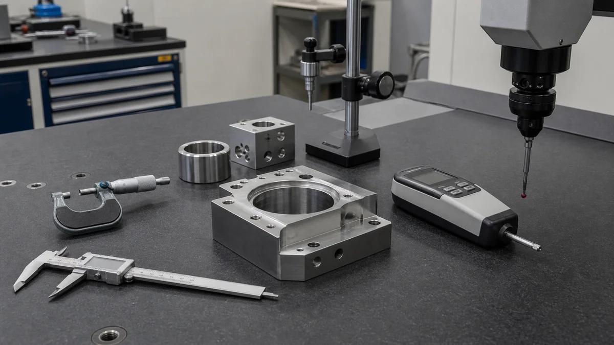
Use the simplest inspection method that can evaluate the stated requirement with suitable access and repeatability. The buyer should define the result and evidence needed, then allow the supplier to propose a method unless the contract genuinely requires a particular approach.
| Feature or requirement | Suitable method category | Specification issue to review |
|---|---|---|
| Accessible outside size | Caliper- or micrometer-type measurement | Contact location and feature accessibility |
| Bore or fitted diameter | Bore measurement or suitable gauge | Depth, roundness, and measurement location |
| Hole-pattern position | Coordinate-based measurement | Datum alignment and complete pattern evaluation |
| Flatness or orientation | Structured surface measurement | Support condition and datum establishment |
| Hidden feature | Coordinate, optical, or dedicated gauging | Probe, line-of-sight, or gauge access |
| Surface roughness | Roughness measurement | Trace direction and controlled surface zone |
A coordinate measurement result is not automatically complete. The CMM inspection report4 should still identify the characteristic, nominal requirement, tolerance, actual result, datum alignment where applicable, and acceptance status. “CMM checked—pass” provides little more value than a generic checkmark.
Geometry after workholding release also matters. Thin walls, broad plates, and flexible plastic parts may change shape after unclamping. The drawing or RFQ may need to state whether inspection occurs in a free state, restrained condition, or agreed fixture. Measurement access can also influence the manufacturing plan: a deep pocket or hidden undercut may be machinable but difficult to inspect with the specified method.
Do not demand coordinate measurement for every dimension without considering value. Routine accessible sizes may be checked efficiently by another suitable method. Tight hole patterns, profiles, and multi-face relationships usually deserve a more structured plan because datum alignment, not just feature size, controls acceptance.
What Equipment and Measurement Conditions Should Be Recorded?
For characteristics requiring traceable measurement evidence, record the inspection instrument, equipment identifier, calibration or verification status, inspection date, and operator. Where temperature, support, conditioning, or restraint can influence the result, define and record the agreed measurement condition rather than comparing uncontrolled readings.
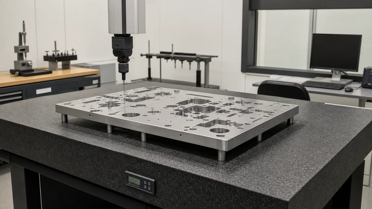
Equipment identification shows how a value was obtained and whether the instrument was within its defined control period. The report does not need to reproduce an entire calibration history. It does need enough information to connect a critical result to the relevant equipment record when traceability is required.
Useful fields include:
- Instrument or measurement-system type
- Unique equipment identifier
- Calibration status or verification period
- Inspection date and responsible operator
- Measurement units and resolution where relevant
- Environmental or conditioning information when specified
- Part support, restraint, or free-state condition when geometry is affected
Temperature deserves attention for close tolerances, long spans, large plates, and precision hole patterns. Aluminum thermal movement can become relevant as tolerances tighten, particularly when machining, inspection, receiving, and service environments differ. The RFQ should state the reference or acceptance condition when that difference could alter disposition; it should not add an arbitrary environmental requirement to every dimension.
Other conditions may be equally important. Nylon can change size with moisture, so the drawing may need an agreed conditioning and inspection state. A thin CNC machined wall may show different flatness while clamped, supported, or free. A plated or anodized bore may need final measurement after treatment because finish buildup affects the accepted size.
When buyer and supplier readings disagree near a limit, compare the measurement uncertainty and conditions5 before concluding that either value is wrong. Check equipment identity, current status, part temperature, cleanliness, support, measurement location, and method. Scale this documentation to feature risk; ordinary clearance dimensions rarely need the same environmental record as a critical fit.
What Material Traceability Evidence Should Accompany the Report?
Require material evidence separately from dimensional results whenever grade, condition, heat lot, source, or properties form part of acceptance. State the exact documentation in the RFQ, such as an MTC or MTR, and define whether substitutions or source changes need approval before production.
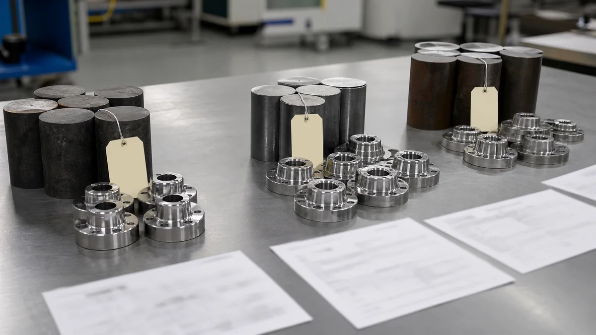
A part can meet every measured dimension and still be made from the wrong alloy, temper, condition, or stock source. Material verification belongs in the quality package as a separate evidence stream tied to the part or production lot.
Specify only the controls the order needs:
- Exact material grade and condition or temper
- Required stock form when it affects function
- MTC, MTR, or another named material record
- Heat lot or batch traceability
- Chemical or mechanical property evidence when contractually required
- Buyer-supplied material status
- Approved-source restrictions, if applicable
- Procedure for requesting substitutions
Avoid asking only for “material certification.” That phrase may not tell the supplier which document, properties, or traceability connection the buyer expects. If heat-lot traceability is required, the receiving package should connect the material test report6 to the delivered lot rather than present an unrelated record.
Material condition also affects manufacturing and inspection planning. Aluminum grade and temper can influence stability and finishing response. Stainless grades can change sourcing and machining assumptions. Engineering plastics may require stock or conditioning information because temperature or moisture can alter final dimensions.
Equivalent-material language needs an approval route. Define which properties must remain unchanged, who can approve the substitution, and whether a source or material change triggers targeted inspection or a renewed FAI review. Do not let equivalence become an informal purchasing decision after machining has begun.
Traceability adds procurement, segregation, verification, and reporting effort. Include it before quotation so the supplier can price and plan the required controls rather than treat the records as an unplanned delivery condition.
Which Finish and Special-Process Results Require Documentation?
Require documented results or supporting records for every finish or special-process characteristic that controls acceptance, including specified roughness, hardness, heat treatment, anodizing, passivation, coating thickness, or cleanliness. Identify the affected surface, required condition, inspection timing, and whether final dimensions apply before or after processing.
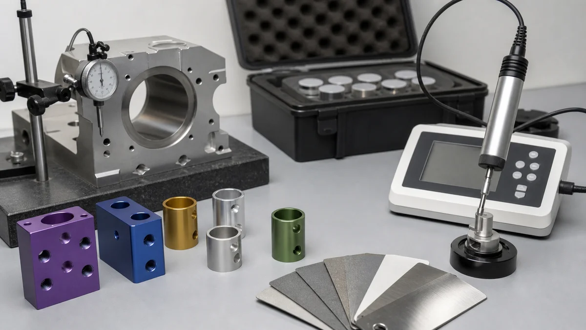
Final dimensional inspection cannot prove that a secondary operation produced the specified surface or material condition. Connect each special requirement to an actual result, supporting record, or agreed verification method. Limit the package to requirements stated by the drawing, RFQ, or purchase order.
| Controlled requirement | Evidence to request | Acceptance decision to define |
|---|---|---|
| Surface roughness | Measured Ra and inspection location when required | Which functional surface is controlled? |
| Hardness | Result and applicable test location or lot basis | Does acceptance apply after final treatment? |
| Heat treatment | Process evidence and final material condition | Which dimensions need post-treatment verification? |
| Anodizing or passivation | Supporting process record | Which surfaces are treated or masked? |
| Coating thickness | Recorded result where specified | Do fitted dimensions apply after coating? |
| Cleanliness | Agreed verification result | What observable or measured condition defines acceptance? |
Localize finish requirements. Sealing faces, sliding surfaces, bearing journals, and visible cosmetic faces may need controlled conditions, while ordinary machined areas may not. A blanket finish note can expand machining and inspection without clarifying what function it protects.
Scenario: A fitted aluminum bore is machined and then anodized. The drawing gives a bore tolerance but does not say whether it applies before or after finishing. Buyer and supplier can reach different conclusions from the same part. The RFQ should define the final dimensional condition, masking, inspection timing, and allowable finish buildup on critical dimensions7.
Heat treatment, coatings, and other external processes can introduce handling, queue, distortion, or renewed-inspection requirements. Define the sequence before quotation so the supplier can plan machining allowance, protected surfaces, final measurement, and supporting evidence as one coordinated route.
When Should You Require a Full or Partial First Article Inspection?
Require a full FAI when an initial production part must demonstrate all applicable design characteristics before routine release. Use a documented partial FAI when a controlled change affects only identified characteristics and related features. Define repeat triggers, report format, sample expectation, and approval responsibility before production.
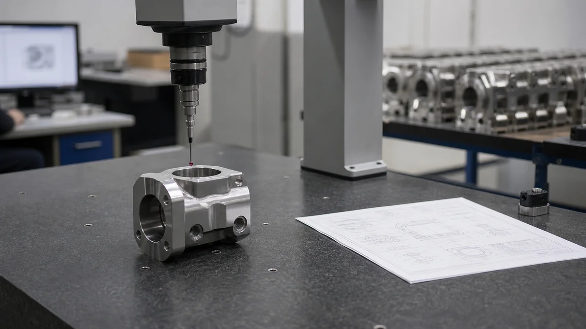
First Article Inspection verifies that an initial production sample conforms to the applicable drawing, specifications, and purchasing requirements. It is especially relevant when a supplier produces a part for the first time and programming, setup, tooling, routing, or drawing interpretation could affect acceptance.
A full FAI addresses all applicable characteristics in the agreed package. A partial or delta FAI may suit a controlled revision that changes only selected requirements while earlier evidence remains valid elsewhere. The reduced scope should identify what changed, which related features were reconsidered, what was reinspected, and why the remaining results were retained.
Define whether review is triggered by:
- A form, fit, or function revision
- A CNC program, fixture, or tooling change with potential effect
- A manufacturing or inspection location transfer
- A material grade, source, or stock-form substitution
- A changed heat-treatment, coating, or other process route
- A significant production lapse defined by the purchasing requirement
- A previous nonconformance requiring renewed approval evidence
The RFQ should state sample expectations, report format, ballooned-drawing requirements, approval timing, and whether routine production may proceed before written acceptance.
Keep First Article Inspection scope8 separate from process capability. One conforming sample shows that the inspected article met the stated requirements at that time. It does not prove that every later part will conform. Repeat production may separately require in-process checks, sampling, selected 100 percent inspection, control records, or capability evidence for identified critical features.
Adding “FAI required” after quotation creates an avoidable scope change. Characteristic-level inspection, report preparation, review, correction, and approval all require planned effort.
How Should Visual Defects and Nonconformances Be Reported?
Require visual findings to identify relevant burrs, scratches, tool marks, contamination, cosmetic damage, or assembly concerns, while keeping dimensional evidence separate. Every rejected characteristic should link to a nonconformance record showing disposition, rework status, approval responsibility, reinspection results, and final acceptance decision.
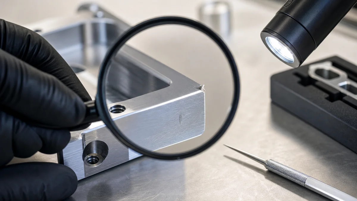
Visual inspection covers conditions that a dimension table may miss. Burrs can obstruct assembly, affect edge safety, or remain inside intersecting passages. Tool marks may matter on sealing, sliding, or visible surfaces. Contamination and handling damage can compromise finishing or final use. The drawing should separate functional surface requirements from cosmetic expectations so acceptance is not based on phrases such as “good finish” or “no visible defects.”
Record the affected location, observed condition, inspection status, and applicable acceptance note or reference. Photographs can support a finding when appropriate, but they do not replace dimensional, roughness, material, or special-process evidence.
For sheet processes, burr direction and formed geometry require process-specific language. CNC turret punching and metal stamping can leave direction-dependent burrs; stamped or bent features can also be influenced by springback. Those are not CNC machining characteristics and should appear only when the order actually uses those processes.
When a result is outside its limit, preserve the original value and follow a visible nonconformance disposition process9:
- Identify the characteristic and actual result.
- Reference the nonconformance record.
- Record the proposed disposition and approval authority.
- Document authorized rework or repair.
- Reinspect affected and related characteristics.
- Record final values and acceptance status.
A corrected final value should not erase the original finding. The buyer also needs to define who can approve use-as-is, rework, repair, or rejection. A supplier should not assume customer approval for a deviation, and receiving inspection should not be the first place undocumented rework becomes visible.
What Inspection Requirements Belong in the CNC Machining RFQ?
Define the inspection package in the RFQ before suppliers quote. Identify the manufacturing process, controlled files, material, critical characteristics, reporting scope, sampling or part coverage, FAI requirements, secondary-process evidence, revision, and delivery expectations. Clear inputs let suppliers price manufacturing and inspection against the same acceptance basis.
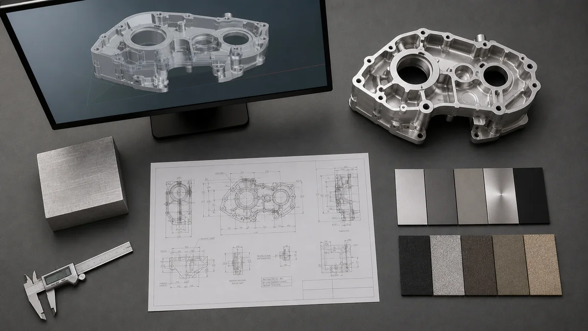
Name the process first. CNC machining removes material from solid stock through milling, turning, drilling, boring, reaming, and related operations. CNC turret punching and CNC punch press work use programmed punches on sheet. Metal stamping uses dedicated dies. Sheet metal fabrication may combine cutting, punching, bending, welding, and finishing. Plastic injection molding forms polymers in a mold.
“CNC turret punching, CNC punch press, CNC-controlled stamping equipment, or metal stamping depending on the actual process” is not a standard single process. Clarify whether the request means turret punching, a CNC punch press, CNC-controlled stamping equipment, or general die stamping. Inspection priorities differ: machining may emphasize bores, datums, and surface finish; punching may emphasize hole geometry and burr direction; stamping and bending may add springback; molding may add wall thickness, draft, gate location, and molded-surface requirements.
Use this CNC machining RFQ checklist10:
- Confirm the intended manufacturing process.
- Send the current 3D model and controlled 2D drawing.
- State which file governs if they conflict.
- Identify part number, drawing number, units, and revision.
- Specify material grade, condition, and traceability.
- State quantity and prototype, pilot, or production intent.
- Mark functional, assembly, cosmetic, and non-critical features.
- Define critical tolerances and applicable GD&T datums.
- Identify surface finish, edge, coating, heat-treatment, and masking requirements.
- State whether dimensions apply before or after finishing.
- Define FAI, full-report, critical-feature, sampling, or per-part inspection scope.
- Specify actual values, ballooned drawing, CMM data, and supporting records.
- Define nonconformance notification and approval responsibility.
- State report format, submission timing, and delivery expectations.
Inspection affects setup planning, measurement access, reporting, and review effort. Defining it before quotation lets suppliers plan suitable methods and price the complete acceptance package without contingency assumptions.
For a manufacturing and inspection recommendation, send the 3D model, controlled 2D drawing, material grade, quantity, prototype or production intent, critical tolerances, surface finish, inspection expectations, revision level, and delivery requirements. Also identify any FAI, material-traceability, special-process, sampling, and report-format requirements before requesting a quotation.
References
- AS9102 FAI (First Article Inspection) - Is a Ballooned Drawing ... - AS9102 does not require a ballooned drawing. It requires that every design characteristic requirement is accounted for, uniquely identified and has inspection ... ↩
- Basic Dimensions and How to Report | GD&T Basics - Basic dimensions are used to locate True Positions. There is no tolerance or deviation in the basic dimensions themselves, as they are theoretically perfect. ↩
- Version Control for Engineering Drawings | Revision Guide - This block is the official record of the drawing's revision history and should include: Revision letter or number Date of revision Description ... ↩
- Discussion of Statistical Issues in Geometric Feature Inspection ... - A coordinate measuring machine (CMM) is a computer controlled device that uses a probe to obtain measurements on a manufactured part''s surface, ... ↩
- [PDF] Handbook 143 2007 Section 6.1 - The temperature variation should be less than ± 1 °C over 24 h and ± 0.5 °C. Other environmental conditions may be acceptable as long as the effects are ... ↩
- How to Read a Material Test Report (MTR) & Heat Number - Matching the heat number on the material to its MTR is vital. It helps verify compliance, traceability, and quality assurance. Interpreting ... ↩
- How Anodizing Affects Dimensions | Build-Up vs Penetration - The total anodize thickness is the sum of both. This dimensional change must be considered during machining to ensure parts meet final engineering ... ↩
- First Article Inspection Reports - FAI - InspectionXpert - A Partial FAI/Delta FAI is conducted when isolated changes are made, such as drawing changes after a change in the part design, or if a previous FAIR recorded ↩
- Non-Conformance Report & Dispositions Process - This disposition is for non-conforming material that can be reworked without adverse effect on safety, performance, interchangeability, reliability, or quality. ↩
- CNC Machining RFQ Template Guide - uneed - Use our checklist for tolerances, parts, and materials. The minimum package for most custom CNC quoting includes the CAD model, PDF drawing, material, ... ↩