CNC machining lead time depends on the complete manufacturing route, not simply the minutes a cutter spends removing material. Material purchasing, CAM programming, fixture preparation, machine scheduling, setup count, secondary operations, inspection, documentation, and unresolved technical questions can all move the shipment date.
Buyers can prevent many delays by defining the process and acceptance requirements before quotation. A strong RFQ separates functional needs from preferences, identifies critical tolerances and finish zones, and states whether the order supports design learning, pilot production, or repeat supply.
The decisions below help buyers expose schedule dependencies, simplify production planning, and compare quotations on a consistent manufacturing basis.
What Does CNC Machining Lead Time Actually Include?
CNC machining lead time includes every activity between receipt of an approved order package and shipment of accepted parts. Material sourcing, programming, fixture preparation, queue time, machining, secondary operations, inspection, documentation, and packing can all determine the delivery date.
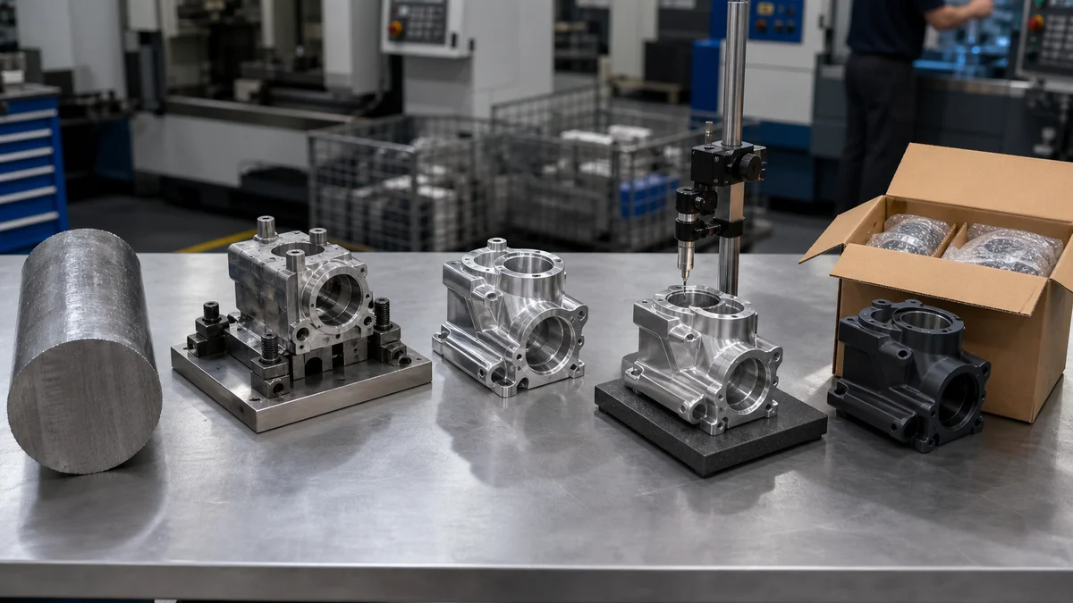
A useful quotation defines when the schedule starts and what condition marks completion. The clock might begin when the supplier receives the purchase order, resolves technical questions, or confirms material availability. Completion might mean machining is finished, final inspection is approved, or packed parts are ready for dispatch. These milestones are not interchangeable.
| Production stage | Required buyer input | Schedule risk if unresolved |
|---|---|---|
| Order review | Matching model, drawing, part number, and revision | Programming waits for clarification |
| Material sourcing | Exact grade, condition, stock form, and documentation | Purchasing or substitution approval delays release |
| Programming and setup | Accessible geometry, datums, and critical relationships | Additional fixtures or orientations appear after quoting |
| Machining | Critical tolerances, surface finish, and feature priority | Toolpaths and inspection points remain uncertain |
| Secondary processing | Treatment, masking, and post-finish dimensions | Outside routing is omitted from the delivery plan |
| Inspection | Characteristics, sample scope, and required records | Completed parts wait for measurement or approval |
| Packing and dispatch | Protection, labeling, and partial-shipment rules | Accepted parts cannot be released |
A part can be fully milled yet still await anodizing, dimensional verification, documentation, or protective packing. Calling that milestone “machining complete” may be accurate, but it is not a shipment commitment.
For delivery-sensitive work, request a process-level schedule that shows the main route and approval gates. It need not disclose private shop details. It should identify buyer-supplied information, outside services, and decisions that can stop work. This is the practical value of manufacturing lead time planning1: it separates controllable specification issues from the supplier’s production queue.
Is CNC Machining the Correct Process for the Part?
Confirm the manufacturing process before comparing lead times. CNC machining removes material from solid stock, while turret punching, metal stamping, sheet metal fabrication, and plastic injection molding use different material forms, tooling strategies, geometry rules, and production routes.
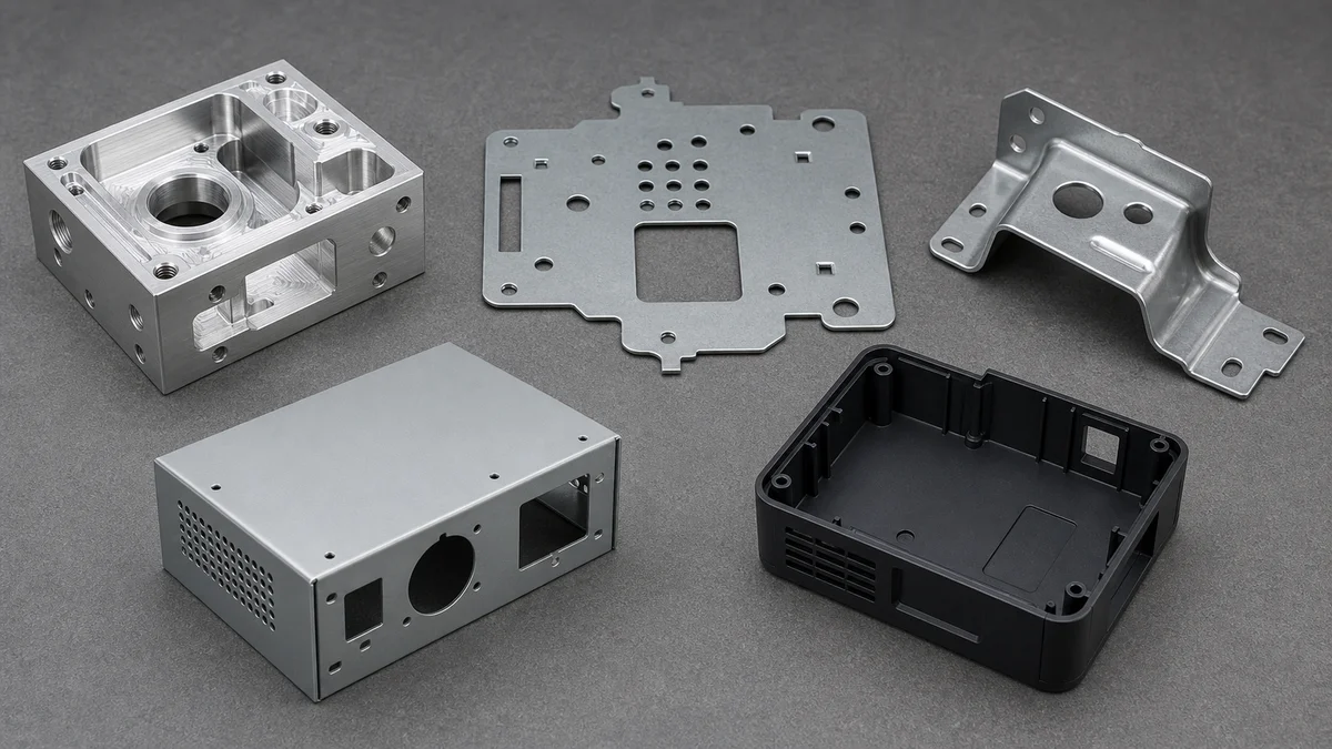
Process selection should follow material form, geometry, tolerance, quantity, and production intent. A lead-time comparison is unreliable when the buyer and supplier are planning different manufacturing methods.
| Process | How the part is made | Specifications that shape the route |
|---|---|---|
| CNC machining | Material is removed by milling, turning, drilling, boring, or reaming | Stock grade, cutter access, setups, tolerances, surface finish |
| CNC turret punching or CNC punch press work | Programmed punch tools cut or form sheet metal | Sheet grade and thickness, tooling, formed features, burr direction |
| Metal stamping | Dedicated dies cut or form sheet metal | Strip material, die sequence, springback, formed geometry, production volume |
| Sheet metal fabrication | Cutting, punching, bending, welding, and finishing may be combined | Bend geometry, joints, weld access, finish, assembly sequence |
| Plastic injection molding | Molten polymer is formed in a mold | Resin, wall thickness, draft, gate location, ejection, tooling risk |
“CNC turret punching, CNC punch press, CNC-controlled stamping equipment, or metal stamping depending on the actual process” is not one standard process term. It may refer informally to CNC turret punching, a CNC punch press, CNC-controlled stamping equipment, or general metal stamping. Replace it in the RFQ with the intended operation.
Example: A sheet-metal bracket with bends and a controlled burr direction should not automatically be quoted as a part machined from solid plate. The sheet route must address bend sequence and springback. Conversely, a housing with deep pockets, sealing faces, and precision bores is not a simple punched-sheet component.
When two routes appear feasible, request separate options. Each should state the material form, tooling assumptions, secondary operations, inspection plan, quantity basis, and revision risk. That creates a valid manufacturing process comparison2 without treating unlike methods as substitutes.
Which Geometry Features Increase Setup and Machining Time?
Geometry extends lead time when it restricts cutter access, requires long tools, creates unstable features, or forces repeated part reorientation. Deep pockets, undercuts, thin walls, small internal radii, and controlled relationships across several faces deserve DFM review before release.
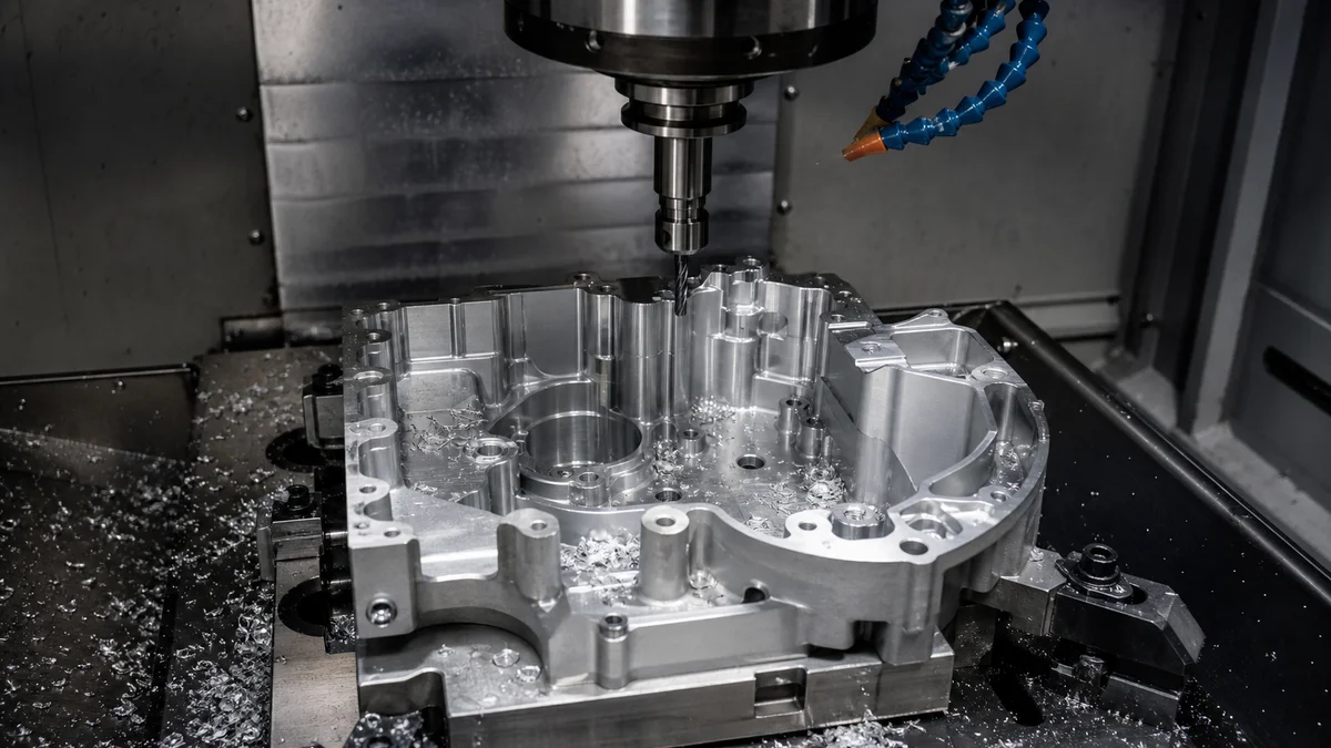
A part is difficult to machine when the cutter, holder, fixture, or inspection method cannot reach a feature directly while preserving its relationship to the functional datums. Visual complexity alone is a poor guide.
Review these setup-driving features before quotation:
- Deep pockets and narrow cavities: Long tool reach reduces rigidity and makes chip evacuation harder. The route may need lighter cuts, additional finishing passes, or another approach direction.
- Small internal corner radii: Milling cutters are cylindrical, so they cannot create perfectly sharp internal corners directly. Small radii force smaller, less rigid tools. Reuse larger radii where mating clearance permits.
- Undercuts and hidden details: These can require special tooling, extra orientations, or multi-axis access. Section views should reveal geometry obscured in the external model.
- Thin walls and tall ribs: Flexible features may deflect or vibrate during cutting. State the required wall thickness and identify surfaces unavailable for clamping.
- Features on several faces: Reorientation adds workholding, alignment, datum transfer, and possibly intermediate inspection. Mark the cross-face position, perpendicularity, or profile controls that actually protect function.
- Nonstandard holes and threads: Standard sizes can reduce special-tool assumptions and tool changes where the joint or flow requirement allows them.
A common specification mistake is demanding a sharp pocket corner even though the mating part has clearance. The supplier must pause to determine whether corner relief, a secondary operation, or a model revision is acceptable.
Ask the supplier to mark restricted cutter access3 and setup-driving geometry during DFM review. The design can then preserve functional interfaces while simplifying cosmetic pockets, unnecessary depth, redundant orientations, or features that create avoidable datum transfers.
How Should Material Grade and Stock Availability Be Specified?
Specify the exact material grade and condition before quotation, then confirm stock availability and documentation requirements. A broad label such as aluminum, stainless steel, or plastic leaves sourcing, machinability, finishing response, dimensional stability, and acceptance assumptions unresolved.
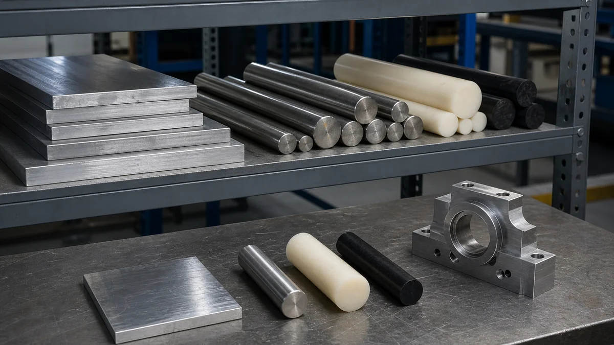
Material identification must be specific enough for purchasing and process planning. For metals, the RFQ may need the alloy, temper or hardness condition, product form, and any required stress-relieved condition. For engineering plastics, grade, reinforcement, supplied condition, and functionally important color may matter. Each requirement should follow the design need rather than a generic preference.
Availability and machinability are separate questions. A technically suitable alloy may not be stocked in the required bar, plate, tube, or billet size. Another grade may be available but require a different cutting strategy, workholding plan, or distortion review. Confirm both stock and process fit before accepting the schedule.
May the supplier propose an alternative?
If substitution is possible, define the properties that cannot change and require approval before purchase. Do not infer equivalence from a broad material family. Strength, corrosion behavior, wear, temperature exposure, dimensional stability, anodizing response, and required material evidence can all affect suitability.
A drawing that says only “aluminum” leaves the supplier to assume the grade, temper, stock form, finishing response, and delivery documentation. Adding those details after material purchase or CAM preparation can invalidate the original route.
The RFQ should also state whether material is supplier-purchased or buyer-supplied, whether source restrictions apply, and which records must accompany the shipment. Where availability threatens the schedule, request stock confirmation before purchase-order acceptance. Good material grade specification4 turns an uncertain sourcing assumption into a controlled manufacturing input.
Which Features Truly Require Tight Tolerances or GD&T?
Reserve tight tolerances for features that control fit, sealing, alignment, motion, or assembly. Use clear datums and GD&T when relationships between features matter, because blanket close tolerances add machining and inspection effort without communicating functional intent.
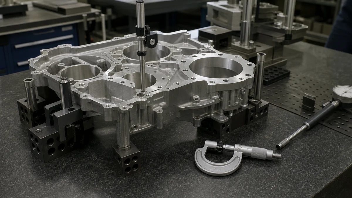
Tolerance planning should begin with feature function. Bearing bores, sealing faces, press-fit areas, dowel holes, alignment features, and mating surfaces may justify close control. Clearance pockets, lightening cuts, cosmetic edges, and non-contact surfaces usually need a different tolerance tier.
| Feature role | Suitable specification approach | Manufacturing consequence |
|---|---|---|
| Functional size | Local size tolerance and relevant surface finish | May require controlled finishing passes and recorded measurement |
| Assembly relationship | Functional datums with position, perpendicularity, parallelism, or profile | Controls setup references and inspection alignment |
| Cosmetic surface | Local visual or roughness requirement | May require protected handling or secondary finishing |
| Non-critical geometry | General drawing tolerance where appropriate | Supports standard machining and inspection planning |
For many non-critical aluminum features, ±0.10 mm to ±0.13 mm can be a practical general-tolerance baseline when tighter control is unnecessary. It remains dependent on supplier, geometry, and part envelope; it is not a universal capability. Put the general tolerance in the drawing notes or title block, or reference an appropriate standard where applicable.
An aluminum feature below about ±0.05 mm should be treated as a combined machining and inspection decision. Workholding stability, tool wear, machine warmup, thermal movement, feature size, and measurement method may become significant. On long spans or large hole patterns, the RFQ may also need an agreed reference temperature.
A frequent mistake is tightening every linear dimension when the real requirement is true position of a hole pattern relative to a mating face. That approach compounds tolerance stack-up without defining assembly intent. Clear datums and geometric tolerancing5 let the supplier plan the setup and verification around the relationship that matters.
What Inspection and Documentation Scope Should the Order Require?
Inspection scope should match feature and acceptance risk. Define which characteristics require measurement, which parts are inspected, what records must be delivered, and when approval is required so measurement access, metrology, and reporting are included in the schedule.
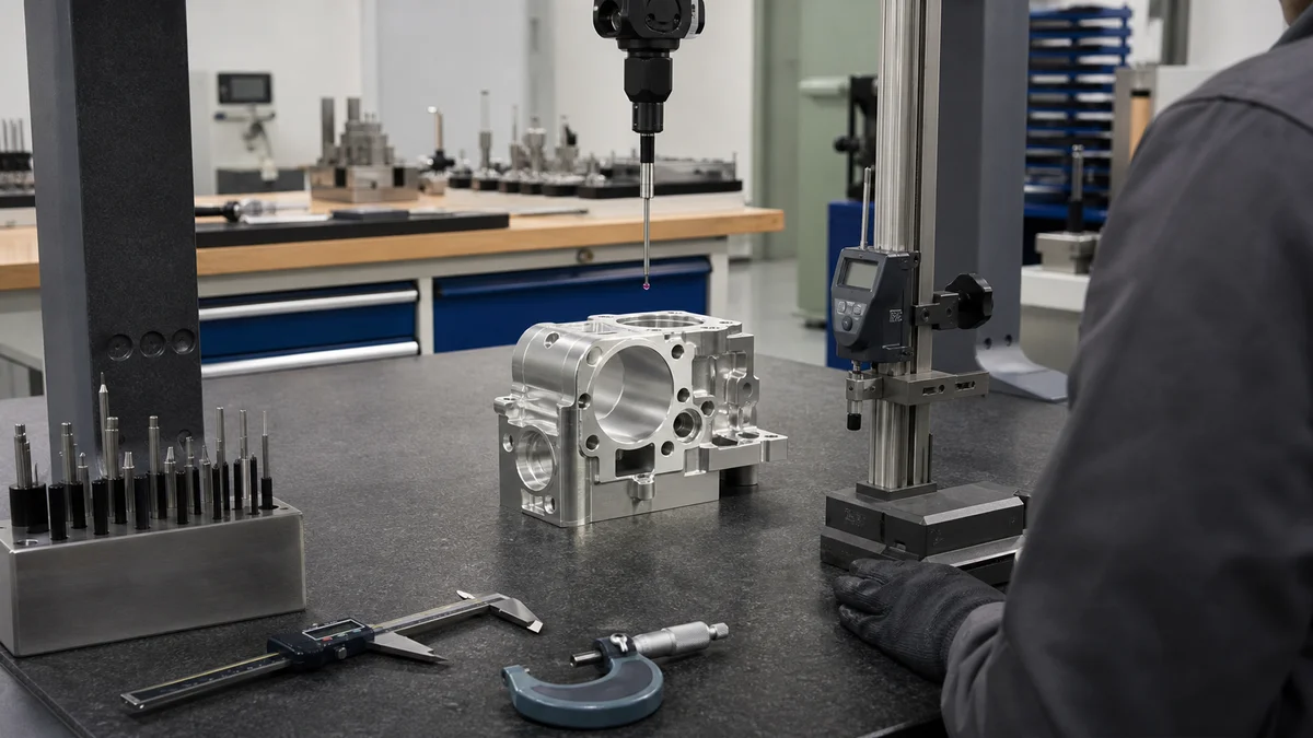
Inspection is part of production, not paperwork added after machining. An accessible outside diameter may suit a micrometer, while a multi-face position requirement, tight hole pattern, flatness control, or localized surface roughness may need a more structured method. Geometry, tolerance, datum structure, access, quantity, and production intent should determine the approach.
Approve these decisions before order release:
- Identify each critical characteristic that needs a recorded result.
- State whether the report covers all drawing characteristics or selected features.
- Define whether the scope applies to a first article, a batch sample, selected features on every part, or another agreed sample.
- Supply the governing revision and any controlled ballooned drawing or feature index.
- For GD&T, state the applicable datum reference frame and the geometric deviation to be reported.
- Require actual measured values where pass/fail alone would not show proximity to a limit.
- Separate dimensional evidence from material, hardness, coating, or roughness records.
- Define report format, review responsibility, and the approval point in the route.
- Establish how nonconforming results, rework, and deviations will be documented and approved.
“Full inspection report required” is too vague by itself. It does not define the sample, characteristics, values, datum alignment, or release timing. Requiring one inspection technology for every feature can also add work without improving acceptance confidence.
The supplier should connect every required record to a controlled drawing characteristic. Adding first-article approval or extensive reporting after machining starts can require renewed measurement or prevent shipment. A clearly defined inspection scope lets metrology effort enter the quotation instead of appearing as a late approval bottleneck.
How Should Finishing and Secondary Operations Enter the Schedule?
Every required finish or secondary operation should appear in the quoted production route. Define treated surfaces, masking, cosmetic criteria, dimensional condition, inspection evidence, transport, and final acceptance rather than assuming parts can ship immediately after machining.
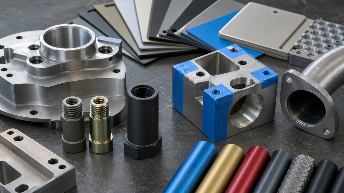
Secondary operations can alter dimensions, surface condition, handling requirements, and inspection sequence. They may also depend on an outside processor whose availability and transport arrangements sit outside the machining supplier’s direct production queue.
| Operation | Drawing or RFQ inputs | Routing and acceptance decision |
|---|---|---|
| Heat treatment | Final material condition, treated zones, critical final dimensions | Decide whether roughing, treatment, and finish machining are separate stages |
| Anodizing or plating | Finish type, finish zones, masking, cosmetic surfaces | State whether dimensions apply before or after finish buildup |
| Bead blasting or polishing | Surface zones, directionality if relevant, visual criteria | Establish sequence relative to coating and final handling |
| Painting | Coverage, masking, cosmetic criteria, protected interfaces | Define when inspection and packing may occur |
| Passivation | Applicable material and required treated condition | Identify any supporting process record required for acceptance |
| Marking or assembly | Mark location, controlled content, installed components | Decide whether final inspection occurs before or after assembly |
Finish controls should be localized. A specified Ra value may be necessary on a sealing face, bearing interface, or sliding surface, while unrelated faces can remain at a normal machined finish. A blanket note can add slow finishing passes, polishing, masking, or roughness measurement without improving function.
A bore specified at final size but not identified as a pre-finish or post-finish dimension creates ambiguity when anodizing or plating adds finish buildup. The machinist and finisher may otherwise apply different acceptance assumptions.
Ask who controls each outside operation, transport step, incoming check, and final release. The delivery commitment should end after the specified treatments, post-process inspection, documentation, and protective packing. That is the purpose of secondary operation scheduling6: it prevents “machining complete” from being mistaken for “ready to ship.”
How Should Quantity Match Prototype or Production Intent?
Quantity should reflect project stage, revision stability, inspection need, and expected demand. A learning prototype, validation batch, pilot run, and repeat-production order justify different levels of programming, fixturing, material planning, process control, and replenishment preparation.
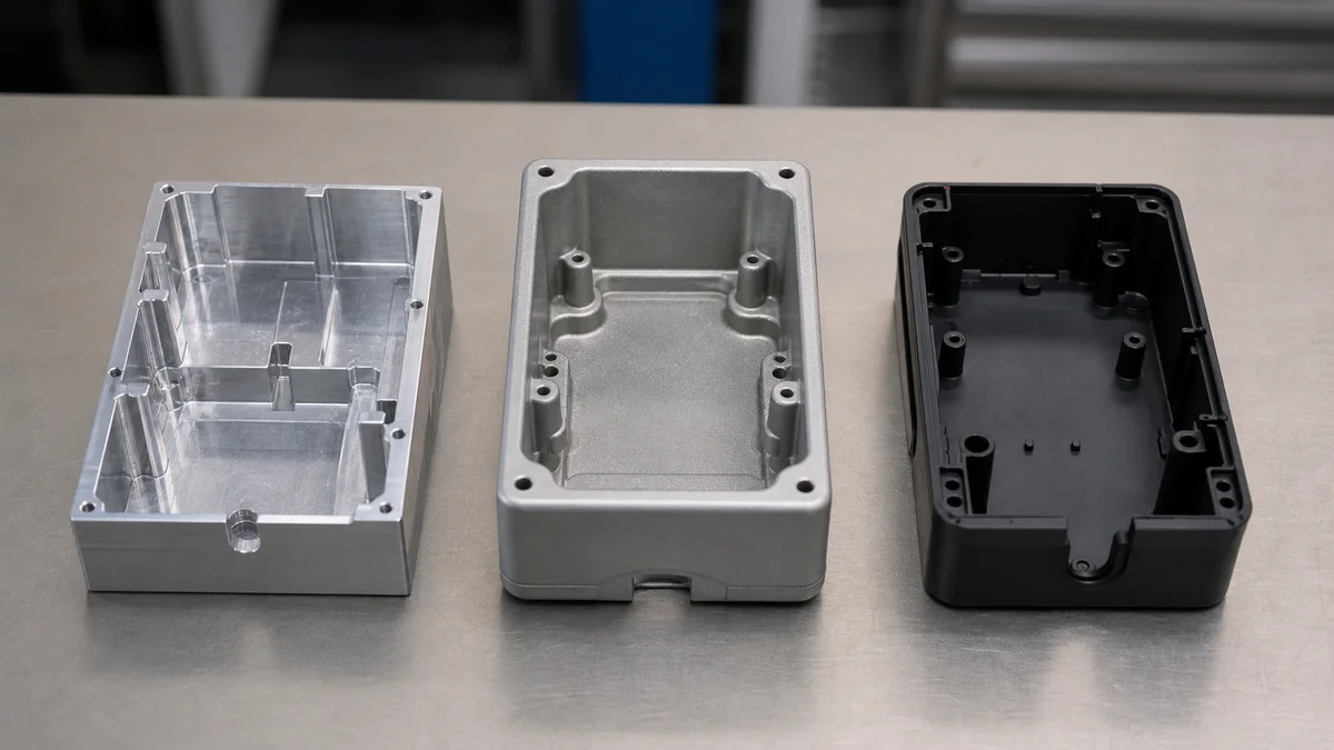
Quantity alone does not define the correct manufacturing plan. The supplier needs to know why the parts are being ordered, what must be learned or validated, and whether the design is stable enough to justify repeatable fixtures or material commitments.
| Production intent | Buyer objective | Appropriate planning focus |
|---|---|---|
| Learning prototype | Review geometry, assembly, or design direction | Flexible workholding and rapid technical feedback |
| Functional validation | Test specified interfaces and performance-related features | Critical tolerances, material condition, and inspection evidence |
| Pilot production | Evaluate repeatability and downstream operations | Stable routing, finishing sequence, workholding, and sampling |
| Repeat production | Supply an established design consistently | Batching, material planning, scheduled releases, and revision control |
A larger batch can spread programming and setup effort across more parts, but it is not automatically the right choice while revisions remain likely. State the immediate quantity, projected usage where known, delivery pattern, and whether partial shipments are acceptable. For repeat parts, forecast visibility or scheduled releases may help the supplier plan stock and production capacity before demand becomes urgent.
Scenario: Machined housing before tooling. A machined aluminum housing is required for fit checks and functional validation, with a possible later transition to die casting or plastic injection molding. The RFQ should identify the design as provisional. Before committing to die or mold tooling, review wall thickness, corner radii, draft, fastening features, cosmetic surfaces, and—in an injection-molded version—possible gate location and ejection needs. A stock-machined prototype does not prove that every feature is suitable for casting or molding.
This production intent statement7 lets the supplier plan a flexible prototype route without assuming that repeat-production fixtures are already justified. Once geometry and acceptance criteria stabilize, pilot and production quantities can be quoted around a more durable tooling, inspection, and replenishment strategy.
How Should Buyers Control Revisions and Technical Questions?
Control revisions by identifying the governing files, current revision, authorized decision-maker, response route, and approval record. Assess every post-order change for its effect on material, programming, tooling, setup, inspection, secondary processing, work in progress, and delivery.
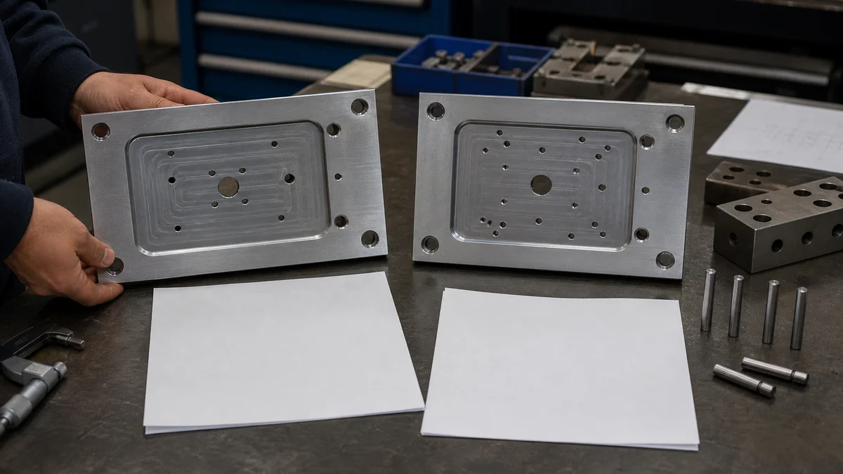
Production cannot advance reliably while the supplier waits for an answer about conflicting requirements. The RFQ and purchase order should establish document authority and a practical clarification route before CAM programming begins.
Use these controls:
- Assign a unique part number and revision to the controlled drawing and model.
- State whether the 2D drawing or 3D model governs when information conflicts.
- Align material, finish, tolerance, inspection, and delivery requirements across the RFQ, drawing, and purchase order.
- Name one authorized technical contact or a clearly defined approval group.
- Record technical questions and approved answers rather than relying on disconnected verbal instructions.
- Replace superseded files in the controlled package and mark obsolete versions clearly.
- Require a schedule-impact review before accepting changes after order release.
- Confirm whether the revision triggers renewed first-article or dimensional approval.
Example: Programming begins from Revision B, but Revision C changes a hole pattern and adds a tighter positional control. Even before cutting starts, the CAM program, fixture references, datum strategy, and inspection plan may need revision. If machining is underway, the impact can extend to work in progress and purchased stock.
Fast answers help, but speed should not bypass control. An immediate instruction from an unauthorized person can create more disruption than a brief formal review. The response should identify the accepted requirement, affected document revision, implementation point, and any disposition for existing parts.
For urgent work, agree in advance who can answer DFM questions and how unresolved issues will be escalated. Effective engineering change control8 keeps technical decisions moving while preserving one auditable definition of the part.
What Must a DFM-Ready CNC Machining RFQ Include?
A DFM-ready RFQ must define the part, material, quantity, production intent, functional requirements, inspection scope, revision, and delivery expectations. It should identify acceptable alternatives so the supplier can resolve sourcing, tool access, setup, finishing, and measurement risks before quoting.
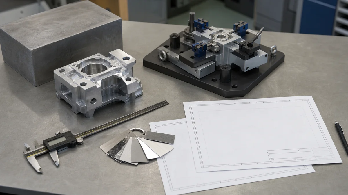
A complete RFQ reduces clarification loops and helps suppliers quote the same scope. It should define required final characteristics without dictating every machining method. The supplier still needs room to propose stock, tooling, workholding, setup, and inspection choices that satisfy the functional requirements.
Use this complete CNC machining RFQ checklist9:
- ☐ Current 3D model in an agreed usable format
- ☐ Controlled 2D drawing with part number and revision level
- ☐ Statement identifying which document governs if model and drawing conflict
- ☐ Exact material grade, temper or condition, and stock-form constraints
- ☐ Required material records and substitution-approval rules
- ☐ Immediate order quantity and realistic future quantity tiers where relevant
- ☐ Prototype, validation, pilot, or repeat-production intent
- ☐ Functional, assembly-related, cosmetic, and non-critical features identified
- ☐ General tolerances, critical size tolerances, functional datums, and GD&T
- ☐ Surface roughness and cosmetic requirements localized to applicable zones
- ☐ Deburring, edge breaks, marking, masking, and secondary operations defined
- ☐ Statement showing whether dimensions apply before or after treatment
- ☐ Inspection characteristics, sample scope, report content, and approval timing
- ☐ Packing, protection, partial-shipment, and delivery expectations
- ☐ Authorized technical contact and formal revision-control route
- ☐ Acceptable material, geometry, finish, or delivery alternatives documented
- ☐ Request for DFM feedback before design or production release
The DFM request should focus on stock availability, cutter access, internal radii, deep features, thin walls, setup count, standard holes and threads, tolerance allocation, finish buildup, and inspection access. It may also ask whether dividing a complex component or changing a non-critical feature would simplify the route.
The package is ready when the supplier can describe the proposed manufacturing sequence, approval gates, and remaining risks without guessing which requirements govern acceptance.
For a process recommendation or quotation, send the 3D model, controlled 2D drawing, exact material grade, quantity, prototype or production intent, critical tolerances, surface finish, secondary operations, inspection expectations, revision level, and delivery date. Mark functional interfaces and identify acceptable material, geometry, finish, or shipment alternatives.
References
- Manufacturing Lead Time Computations (Oracle Bills of Material Help) - Manufacturing Lead Time Computations. Bills of Material computes manufacturing lead times from item, routing and resource availability information. ↩
- CNC Turret Punching Process Overview | PDF | Sheet Metal - Scribd - Turret punching uses a CNC machine to punch holes in sheet metal or plastic according to a CAD design. The turret holds multiple punch tools. Injection Molding ... ↩
- CNC Design Guidelines: Walls, Pockets & Threads (2026) - Deep pockets beyond 3:1 depth-to-width require specialty tooling. Thin walls below 0.040 in. (1.0 mm) need slower feeds and additional finishing ... ↩
- ASM Materials Information FAQ - Features compositions, physical and mechanical properties, and producer information for thousands of alloys specifications, standards, and commercial grades. ... ↩
- GD&T Symbols Chart: All 14 Symbols per ASME Y14.5 | MakerStage - Position is the most commonly used symbol; Profile of a surface can replace separate flatness, parallelism, perpendicularity, and position callouts ↩
- How Can I Ensure the Dimensions of Parts After Hard Anodizing? - 1. Adjust CNC Machining Dimensions Based on Anodizing Growth. To ensure final dimensional accuracy, it's crucial to pre-compensate for changes introduced by ... ↩
- Product Development Cycle - Sigma Design - Below we explore our approach to the various stages of Product Development, which includes: Proof of Concept, Prototype, Pilot and Production. ↩
- Engineering Drawing Revision Control: Stop Production Delays - This structure follows ASME Y14.35, the standard governing revision of engineering drawings and associated documents. It helps ensure that ... ↩
- CNC Machining RFQ: 6 Steps to Avoid Costly Quote Delays - Streamline your CNC machining RFQ process with clear CAD data, material specs, surface finishes, delivery terms, and DFM checks before ... ↩